Page 10: The Analog Domain: Transistors
Unit 6, Lab 1, Page 10
MF: lightly clean up to cut down on the boxes
On this page, you’ll learn about the transistors that implement logic gates.
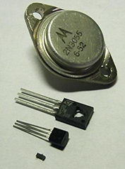
The transistor is the fundamental building block of electronic circuits, where they are used as on/off switches.

Image by sv.Wikipedia user DaRy
You’ve learned that a wire can either have a voltage or not have a voltage on it. The reality is more complicated. The on-or-off picture of a wire, a transistor, or a logic gate output is a simplification—an abstraction.

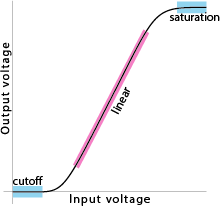
This is a rough graph of the actual input-output behavior of a transistor. Don’t worry about the details; just notice the two blue flat parts of the graph. Within the “cutoff” region, small changes to the input voltage do not change the output voltage at all; the output is always zero volts. Likewise within the “saturation” region, small input changes hardly impact output voltage; the output is interpreted as a one. This is how transistors are used as switches in a computer.
Transistors are versatile devices. When used in the middle, linear (pink) part of the graph, they’re amplifiers; a small variation in input voltage produces a large variation in output voltage. That’s how they’re used to play music in a stereo.
The transistor was invented in 1947 by John Bardeen, Walter Brattain, and William Shockley at Bell Laboratories, also the home of Unix. The inventors were awarded the 1956 Nobel Prize in Physics for this work.
The digital domain is not a law of nature; circuit designers have to work at ensuring that each wire in a circuit is always either fully on or fully off. The digital domain is an abstraction.
Learn more about what’s below the digital abstraction and how it’s applied.
The flatness of the output at the two extremes is important because there will be small changes in the input. Electrical circuits have “noise,” undesired changes in voltages, for reasons from the transistors getting hot to loose connections on the circuit board to cosmic rays. This is why computers use zeros and ones: a transistor has two flat regions in its input-output curve.
But the flatness of the saturated region is only approximate, and it depends on how the transistor is connected to the rest of the circuit. One example of a potential problem is fanout, the number of transistor inputs to which one transistor’s output is connected. Beyond a certain number (it depends on the particular transistor type, but certainly ten inputs would be too many), the output voltage is reduced to the point that those inputs might not be sure whether they’re getting a zero or a one.
The way a transistor really works depends on quantum physics. (We’re not talking about quantum computers; plain old computer circuits are based on quantum effects also.) To learn more about analog-domain circuit design and what’s inside a transistor, take an Electrical Engineering course.
- Research how transistors are used to implement logic gates.